to drive up to 16 servos
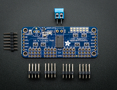
I2C.SPIThe Servo Driver we are talking about here is the Adafruit 16-Channel 12-bit PWM/Servo Driver - I2C interface - PCA9685.
nano, vi, gedit, ...), as root (sudo).
/etc/modules
  i2c-bcm2708
  i2c-dev
Save your modifications, if you have done any.
 Prompt> sudo apt-get install python-smbus
 Prompt> sudo apt-get install i2c-tools
/etc/modprobe.d/raspi-blacklist.conf, comment the two lines it contents:
 blacklist spi-bcm2708
 blacklist i2c-bcm2708
 # blacklist spi-bcm2708
 # blacklist i2c-bcm2708
Save your modifications, if you have done any.
i2cdetect utility, which will will use to know the address of the servo driver:
 Prompt> sudo i2cdetect -y 1
      0  1  2  3  4  5  6  7  8  9  a  b  c  d  e  f
 00:          -- -- -- -- -- -- -- -- -- -- -- -- --
 10: -- -- -- -- -- -- -- -- -- -- -- -- -- -- -- --
 20: -- -- -- -- -- -- -- -- -- -- -- -- -- -- -- --
 30: -- -- -- -- -- -- -- -- -- -- -- -- -- -- -- --
 40: 40 -- -- -- -- -- -- -- -- -- -- -- -- -- -- --
 50: -- -- -- -- -- -- -- -- -- -- -- -- -- -- -- --
 60: -- -- -- -- -- -- -- -- -- -- -- -- -- -- -- --
 70: 70 -- -- -- -- -- -- --
As seen above, the I2C addresses range from 0x03 to 0x77 (binary 0000011 to 1110111). This way, several boards can be used simultaneously from the RasPI, as long as their I2C addresses are different, even if the GPIO interface pins are connected to several different boards.
 Prompt> sudo i2cdetect -y 1
      0  1  2  3  4  5  6  7  8  9  a  b  c  d  e  f
 00:          -- -- -- -- -- -- -- -- -- -- -- -- --
 10: -- -- -- -- -- -- -- -- -- 19 -- -- -- -- 1e --
 20: -- -- -- -- -- -- -- -- -- -- -- -- -- -- -- --
 30: -- -- -- -- -- -- -- -- -- -- -- -- -- -- -- --
 40: 40 -- -- -- -- -- -- -- -- -- -- -- -- -- -- --
 50: -- -- -- -- -- -- -- -- -- -- -- -- -- -- -- --
 60: -- -- -- -- -- -- -- -- -- -- -- -- -- -- -- --
 70: 70 -- -- -- -- -- -- 77
where, in addition to the above,
0x19 would be the magnetometer address (LSM303)0x1e would be the accelerometer address (LSM303)0x77 would be the BMP180 address
|

|

|

The Raspberry PI, connected to a PCA9685, with 2 servos. |
i2cdetect utility.
 Prompt> sudo i2cdetect -y 1
      0  1  2  3  4  5  6  7  8  9  a  b  c  d  e  f
 00:          -- -- -- -- -- -- -- -- -- -- -- -- --
 10: -- -- -- -- -- -- -- -- -- -- -- -- -- -- -- --
 20: -- -- -- -- -- -- -- -- -- -- -- -- -- -- -- --
 30: -- -- -- -- -- -- -- -- -- -- -- -- -- -- -- --
 40: 40 -- -- -- -- -- -- -- -- -- -- -- -- -- -- --
 50: -- -- -- -- -- -- -- -- -- -- -- -- -- -- -- --
 60: -- -- -- -- -- -- -- -- -- -- -- -- -- -- -- --
 70: 70 -- -- -- -- -- -- --
We will use the 0x40 address to reach the PCA9685.
PCA9685. Check it out in the repository. We are going to comment only on the main method of this class, which is a basic example. It assumes that 2 servos are connected to the PCA9685, on the 15 and 14 slots.
  ...
  public static void main(String[] args)
  {
    PCA9685 servoBoard = new PCA9685();   // 0x40 is the default address
    servoBoard.setPWMFreq(60); // Set frequency to 60 Hz
    int servoMin = 150;   // Min pulse length out of 4096
    int servoMax = 600;   // Max pulse length out of 4096

    final int CONTINUOUS_SERVO_CHANNEL = 14;
    final int STANDARD_SERVO_CHANNEL   = 15;

    for (int i=0; i<10; i++)
    {
      System.out.println("i=" + i);
      servoBoard.setPWM(STANDARD_SERVO_CHANNEL,   0, servoMin);
      servoBoard.setPWM(CONTINUOUS_SERVO_CHANNEL, 0, servoMin);
      waitfor(1000);
      servoBoard.setPWM(STANDARD_SERVO_CHANNEL,   0, servoMax);
      servoBoard.setPWM(CONTINUOUS_SERVO_CHANNEL, 0, servoMax);
      waitfor(1000);
    }
    servoBoard.setPWM(CONTINUOUS_SERVO_CHANNEL, 0, 0); // Stop the continuous one
    System.out.println("Done with the demo.");
  }
  ...
This code loops 10 times and makes the servos go from a value of 150 to a value of 600, and vice versa.
It waits for 1000 milliseconds between each message to the servos.
int variables, CONTINUOUS_SERVO_CHANNEL and STANDARD_SERVO_CHANNEL.
minServo is 150.
maxServo is 600.
TickTime = 1 / (freq * 4096).PulseTime = TickTime * nbTicks.| Pulse Width in ms | Nb Ticks |
|---|---|
| 1 | 246 |
| 1.5 | 369 |
| 2 | 492 |
$I2C.SPI> ../gradlew clean shadowJar
You can run the code from a script named servo:
 #!/bin/bash
 CP=./build/libs/I2C.SPI-1.0-all.jar
 sudo java -cp $CP i2c.servo.pwm.PCA9685
Prompt> ./servo
And here is the result
 Prompt> ./servo
 Connected to bus. OK.
 Connected to device. OK.
 Setting PWM frequency to 60 Hz
 Estimated pre-scale: 100.72526
 Final pre-scale: 101.0
 i=0
 i=1
 i=2
 i=3
 i=4
 i=5
 i=6
 i=7
 i=8
 i=9
 Done with the demo
 Prompt>
The console output
|
| For the Standard Servo | Between 122 & 615 ticks |
| For the Continuous Servo | Between 340 & 410 ticks, stop at 375 |
i2c.samples.DemoContinuous and i2c.samples.DemoStandard.